Glowing demo with ShiftPWM and ATMega328P
After first coming across the Dangerous Prototypes Christmas ornament design in the summer, I’ve been thinking about how I might build on the design to make the light show a bit more exciting. One aspect that stuck out for me was how all 10 LEDs flash on and off at once. I decided my goal should be to have individual control over as many LEDs in the Christmas tree as possible.

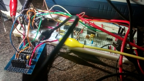
Two shift registers connected to an Arduino
My first experiment solving the problem envisioned one or two 74HC595N Serial In Parallel Out shift registers. A nice glowing PWM effect is achieved through PWM via a CTC interrupt function. While I was able to wire this up with my Arduino’s Mega328, the Mega-only ShiftPWM library is too bloated for the tiny13’s 1K. Although the tiny13 Arduino core does have untested ShiftOut() functionality, the shift register idea is out, as the necessary program at my skill level puts it outside of time constraints. Although unsuitable for now, but shift registers have been added to my list of fun future projects.
Another option I considered was charlieplexing, or using the tri-state properties of MCU i/o pins to control 3 LEDs per pin, set up in an array. However, this would also mean current flowing through i/o pins. Scratch this idea, but add it to the experiment list, as it might come in useful later.

How to groups the lights up with transistors
Ultimately, I decided to keep it simple and divide the 10 LEDs into groups of two, expanding from a single transistor switching 10 LEDs to 5 BJTs switching groups of 2 LEDs each. The same interrupt-based PWM technique as mentioned above is used on all 5 tiny13 pins. PB5/Reset is kept free for ISP access. Why not drive the LEDs directly from the tiny13 i/o pins? After all, the combined max current from the LEDs is 40mA, and the max current on a tiny13 pin is also 40mA. Good question.
When approaching hackability from a design perspective, maximizing the useful life of a device is a key focus. Future needs change, and if your design lends itself to being adapted along with that change, it will continue to serve a useful purpose for a long time. Building in tolerance and redundancy above the bare minimum requirements increases resiliency to the unforeseen.
Let’s ignore for a minute the fact that a simple code change to open up all 5 pins puts the tiny IC dangerously close to its 200mA limit of VCC to GND. While the two parallel LEDs on each pin might be enough for our current purposes, what if the LEDs are replaced with a heavier load? The i/o pins would probably be okay with the 2 LEDs at the duty cycle as programmed, but the pins would surely fry driving a motor. On the other hand, the NPNs can handle 600mA of continuous collector current, and might one day the board could be repurposed to power a little robot to amble along for our amusement. Plus, they’re insanely inexpensive. BJTs FTW!

Original schematic with my grouped LED remix
Another concern is the ISP port, which shares the serial lines with two groups of LEDs. The 40mA demand of the LEDs could potentially disrupt the flash programming sequence or damage the programmer. Isolating the load from the serial lines keeps things safe for reprogramming the tiny13.
Pro tip: printouts can be used to match footprints
Minor design changes included moving most of the cluttered components to the back of the board, arranged in a fashion to allow for a small area for a handwritten message at the top of the board. When designing PCBs, using a block of silkscreen can be handy for writing notes on boards. The switch and battery clip were swapped for components I had available. The switch fit an existing part in Eagle (Omron 1000), which made light work of swapping out the original design’s SMD switch in favour of the through-hole I had on hand.

Creating devices from scratch in Eagle is a 3-step process
The battery clip had no datasheet and no part that came close. Out came the caliper and a notebook, then the SMD pad size and spacing were created in Eagle’s package editor. The placement silkscreen with chamfer to indicate polarity was also created. A tip: when replacing components in Eagle’s schematic view, make sure the polarity of the new part matches your diagram. While it wouldn’t have broken the circuit, the silkscreen indicator for positive would have been reversed, creating future confusion.
The final result is a slightly larger (5 * 8 cm) remixed work, with most of the unsightly components moved to the backside. The battery clip and switch are slightly different. The code has been replaced with the interrupt software PWM implemented by funkfinger based on Atmel Application notes. The sleep function from Ian’s code rounds things off to replicate the battery saving functionality. Here is the code from the original Dangerous Prototypes ornament (hopefully those links work for you. If not, please let me know):
http://www.pastebin.ca/2883580
Here’s my frankencode:
http://www.pastebin.ca/2883549
The effect of my circuit and code remix is 5 groups of two LEDs glowing on and off, all at different rates. This produces a pleasing twinkling effect, and is sure to light up the season. As of my writing this, my DirtyPCBs order has been batched and sent to the board house. With any luck, I’ll have an update before Christmas.

Original design, bottom layer

Circuit remix bottom later


