Category Archives: C++

Hackable ornament: my circuit and code remix

IMG_20141115_213311320_HDR

Glowing demo with ShiftPWM and ATMega328P

After first coming across the Dangerous Prototypes Christmas ornament design in the summer, I’ve been thinking about how I might build on the design to make the light show a bit more exciting. One aspect that stuck out for me was how all 10 LEDs flash on and off at once. I decided my goal should be to have individual control over as many LEDs in the Christmas tree as possible.

IMG_20141127_033017255_HDR

Two shift registers connected to an Arduino

My first experiment solving the problem envisioned one or two 74HC595N Serial In Parallel Out shift registers. A nice glowing PWM effect is achieved through PWM via a CTC interrupt function. While I was able to wire this up with my Arduino’s Mega328, the Mega-only ShiftPWM library is too bloated for the tiny13’s 1K. Although the tiny13 Arduino core does have untested ShiftOut() functionality, the shift register idea is out, as the necessary program at my skill level puts it outside of time constraints. Although unsuitable for now, but shift registers have been added to my list of fun future projects.

Another option I considered was charlieplexing, or using the tri-state properties of MCU i/o pins to control 3 LEDs per pin, set up in an array. However, this would also mean current flowing through i/o pins. Scratch this idea,  but add it to the experiment list, as it might come in useful later.

IMG_20141202_212806289_HDR

How to groups the lights up with transistors

Ultimately, I decided to keep it simple and divide the 10 LEDs into groups of two, expanding from a single transistor switching 10 LEDs to 5 BJTs switching groups of 2 LEDs each. The same interrupt-based PWM technique as mentioned above is used on all 5 tiny13 pins. PB5/Reset is kept free for ISP access. Why not drive the LEDs directly from the tiny13 i/o pins? After all, the combined max current from the LEDs is 40mA, and the max current on a tiny13 pin is also 40mA. Good question.

When approaching hackability from a design perspective, maximizing the useful life of a device is a key focus. Future needs change, and if your design lends itself to being adapted along with that change, it will continue to serve a useful purpose for a long time. Building in tolerance and redundancy above the bare minimum requirements increases resiliency to the unforeseen.

Let’s ignore for a minute the fact that a simple code change to open up all 5 pins puts the tiny IC dangerously close to its 200mA limit of VCC to GND. While the two parallel LEDs on each pin might be enough for our current purposes, what if the LEDs are replaced with a heavier load? The i/o pins would probably be okay with the 2 LEDs at the duty cycle as programmed, but the pins would surely fry driving a motor. On the other hand, the NPNs can handle 600mA of continuous collector current, and might one day the board could be repurposed to power a little robot to amble along for our amusement. Plus, they’re insanely inexpensive. BJTs FTW!

before_after_2_schematic

Original schematic with my grouped LED remix

Another concern is the ISP port, which shares the serial lines with two groups of LEDs. The 40mA demand of the LEDs could potentially disrupt the flash programming sequence or damage the programmer. Isolating the load from the serial lines keeps things safe for reprogramming the tiny13.

match footprints with printout

Pro tip: printouts can be used to match footprints

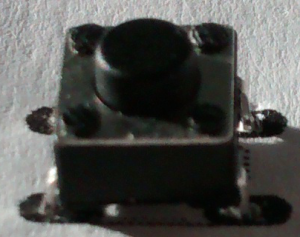
Minor design changes included moving most of the cluttered components to the back of the board, arranged in a fashion to allow for a small area for a handwritten message at the top of the board. When designing PCBs, using a block of silkscreen can be handy for writing notes on boards. The switch and battery clip were swapped for components I had available. The switch fit an existing part in Eagle (Omron 1000), which made light work of swapping out the original design’s SMD switch in favour of the through-hole I had on hand.

battery_device

Creating devices from scratch in Eagle is a 3-step process

The battery clip had no datasheet and no part that came close. Out came the caliper and a notebook, then the SMD pad size and spacing were created in Eagle’s package editor. The placement silkscreen with chamfer to indicate polarity was also created. A tip: when replacing components in Eagle’s schematic view, make sure the polarity of the new part matches your diagram. While it wouldn’t have broken the circuit, the silkscreen indicator for positive would have been reversed, creating future confusion.

The final result is a slightly larger (5 * 8 cm) remixed work, with most of the unsightly components moved to the backside. The battery clip and switch are slightly different. The code has been replaced with the interrupt software PWM implemented by funkfinger based on Atmel Application notes. The sleep function from Ian’s code rounds things off to replicate the battery saving functionality. Here is the code from the original Dangerous Prototypes ornament (hopefully those links work for you. If not, please let me know):

http://www.pastebin.ca/2883580

Here’s my frankencode:

http://www.pastebin.ca/2883549

The effect of my circuit and code remix is 5 groups of two LEDs glowing on and off, all at different rates. This produces a pleasing twinkling effect, and is sure to light up the season. As of my writing this, my DirtyPCBs order has been batched and sent to the board house. With any luck, I’ll have an update before Christmas.

Original design, bottom layer

Original design, bottom layer

Circuit remix bottom later

Circuit remix bottom later

Leave a comment

Filed under Battery power, C++, code, DIY, fabrication, Hacking, ICs, Lights, PCB design

Data over radio to remote display

After fussing with two SPI devices that were not playing nice (namely, the TFT’s ST7735 and the NRF24L01+ radio), I turned my attention again to a graphic LCD module (MTB-368 from ETT Co. in Thailand) found on eBay back in January. Its M68-type parallel interface made it a bit trickier to get going. On top of this, it uses 5V logic, and my Teensy 3.0‘s Kenetis is 3V3. Google’s only hit for a datasheet was mostly in Thai. Thankfully, a quick email to the manufacturer yielded an English manual.

First shot at a 5V GLCD to a 3V3 micro.

Next, finding a library that would allow me to talk to the GLCD with my MCU in at a high level. Thankfully, there were two candidates: openGLCD and u8glib. To correct for the logic voltage level mismatch, I used 10K Ohm resistors in series on the bidirectional data lines. After many hours of fiddling with code and configuration with both candidates, I was no farther along than illuminating the backlight and a few erratic lines through the display.

After posting to the Teensy forum at PJRC, I had contact with the developer behind openGLCD, Bill Perry, and with his help we were able to get the MTB-368 running. One point that was unclear from the GLCD module’s datasheet was whether the CLK pin (not common on SED1520-based controllers) was an input or output. After Bill correcting some timing and initialization sequences, the MTB-368 still wasn’t working, though it was behaving differently.

After looking for more MTB-368 modules online, I noticed the SBN1661 (a cousin to the SED1520) had a similar configuration with its backlight circuitry, and also required a clock. Based on a hunch, and after confirming there was no readable voltage on the pin, I configured my Teensy board to provide a 2kHz square wave (50% duty cycle) by adjusting Timer 1 (pins 3 and 4). With the LCD running on my new bi-voltage UNO, the Teensy was free to experiment with PWM timing. After a rough shot at the right frequency (I do not have a scope — yet), the MTB-368 leapt to life.

Having already done a experiment with a set of nRF240l+ PA/LNA v5.1 radios (recommended: conforms to layout spec), I hooked up the GPS on the client side (UNO) and the display on the server side. Both the Teensy and the UNO communicate with the NRF radio using the RH_NRF24 library and its ReliableDatagram manager. All my experiments to-date have used the library’s default rate of 2.402 GHz (channel 2), 2Mbps, and 0dBm. PA and LNA have not been used.

UNO clone handles the reading & transmitting.

The biggest challenge in sending GPS data over the radio was getting the two fields, latitude and longitude, mashed together with the appropriate separator and passed in the correct format to the radio manager. According to RH_NRF24’s documentation, the data packet buffer requires an unsigned 8-bit pointer (uint8_t*). TinyGPS++ provides an object for every data field in a floating format. Thus my challenge was two-fold: mashing the two together and converting to a binary format needed for the radio manager.

ScreenClip

This project quickly became a study in the differences of micro-controller C versus its big brother running on full computers. The usual suspects for type conversion, including stringstream and lexical_cast, are not included in the anemic version of C++ running under the hood of Arduino. Even heap functions, such as those used by printf in its floating number handling, is unavailable. After getting a grasp on data types, casting, and forming data to satisfy different applications (and compiling without error!), I discovered the hobbled printf wasn’t going to cut it. Fortunately, a quick Google search provided an alternative: dtostrf().

Almost every pin in use on the Teensy 3.0 — 20 in all.

Some more fiddling with proper casting yielded a functional result. Data was received from the other side of the house with virtually no missed packets. Further work includes additional GPS fields, logging on the server, and display layout to maximize data on the screen and minimize refreshes. Experimenting with different channels, signal strength, and data rates. Additional sensors may also be included in the wireless mix.

Data from the remote GPS received over radio and displayed by the server.

Data from the remote GPS received over radio and displayed by the server.

Arduino sketch for the client: http://pastie.org/9381294

Server: http://pastie.org/9381297

Leave a comment

Filed under C++, code, DIY, ICs, micro-controllers, radio, Teensy