OK, maybe not as dramatic, but it was just as vital.
With my final project deadline extended a week, I took a couple days of downtime to catch up on sleep. The all-nighters were adding up. Now I’m back and making some minor changes and a few fixes. Hopefully the thing will drive in reverse without catching on fire. If you don’t hear from me, send help.
Firmware for the not has been fleshed out and I’m looking forward to getting it coded. The loop is simple, checking the status of each input and setting a flag. That flag is passed to the three output functions, which run after the input stage. One exception is the turnaround() function, which is called by an interrupt on the whisker pin. Some output functions call themselves to complete a series of drive commands, for instance. This keeps things simple.
Mounting at the rear, near the motors, his board is centered around a SN754410, a quad half bridge driver. The IC includes clamping diodes, but external Schottky diodes add an extra layer of protection from potentially ruinous flyback current.
Power supply board for my two wheeled robot. 5 and 3.3V provided by TI LDO regulators at 3A each, and fused vbatt for the motors. PPTC rated 3A IH at 12V. Protection from over voltage condition (important when combining motors and MCUs) using crowbar circuits. Divider and space reserved for a tiny85 to monitor battery voltage.
So testing on the first iteration on this board ended in a fit of curses too salty to repeat here. Decided to make another attempt, and incorporate the (painful) lessons from my first try. Opted for non-bussed perf board, and arranged components so their leads could be used to make connections.
Much neater rats nest on the flip side. Watch this post for updates on how this tests out.
Over-voltage protection for each rail of my project’s power supply in the form of a thyristor (silicon controlled rectifier or SCR) based crowbar circuit. The Zener breakdown voltage determines the cut off and trips the gate of the SCR, causing a short condition. The short is then handled by a fuse, protecting sensitive devices. A threshold of about 1V for the Zener diodes (4.3V for the 3.3V rail & 6.2V for the 5V rail) was selected to allow for overhead in case of transient spikes.
The comparator circuit presented in the course detected flex in the sensor for only one direction, as this is a single rail circuit. This presents a challenge, as my robot platform uses a single long whisker straight out the front to detect collision. An obstacle could strike the end of the sensor and bend it in either direction. Thus it is crucial that the micro controller be able to read a flex in the sensor in either direction.
My original flex sensor bridge circuit with comparator front end.
The Question
Having measured the voltage differential across the Wheatstone bridge flex sensor circuit, I noticed that a negative voltage when the sensor was flexed in the direction opposite from what the datasheet advises. It stood to reason that this change in voltage might be detectable.
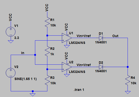
After posting my circuit and question on the discussion board, Thomas_91 was kind enough to supply the following voltage window circuit. It is a dual comparator circuit that detects an upper and lower reference, and gives a HIGH when within the window of the reference and LOW when outside the reference, or the inverse. In my case, I want to measure when the sensor is at rest, and provide a HIGH signal when outside the window. This solves my design problem of wanting to detect a flex in either direction.
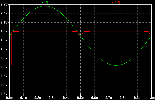
Thomas_91’s circuit posted on the EE40LX discussion board. He used a sine generator to demonstrate the window effect.
Thomas_91 produced a graph to demonstrate the window effect using a sine voltage generator.
SPICEy
Having installed LTSpice but never really used it in solving a problem, I recreated Thomas_91’s circuit, and adapted it for my purposes. Verifying the window and threshold behaviours in simulation, I breadboarded the circuit and included trimpots to adjust the upper ceiling of the voltage reference. The flex sensor is measured with a trimpot for adjustment to its balance.
My voltage window circuit with flex sensor (out of frame) and trimpots.
I created a small program in Arduino to read the output of the dual comparator on a digital pin. After fine tuning the trimpots, I was able to get a very satisfactory sensitivity range.
The Sensor Rig
A nut captive in some hot glue allows mounting on the front end of the robot.
After reading the many comments about how this particular flex sensor can break easily, I followed the instructor’s example and mounted my sensor on a tie wrap. Smooth sided tape was used to fashion a sheath that allows the sensor and tie wrap to bend together without bunching up.
The flex sensor bends together with the tie wrap without bunching up thanks to the green sheath. The sheath is affixed to the tie wrap with hot glue.
Two photo sensors with bridge and comparator front ends. Power supplied by a MCU pin, which switches high only when measurement is needed. This reduces overall power consumption, which is 11.355mW for both bridges.